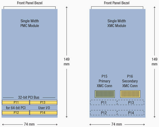
 A PCI Mezzanine Card or PMC is a printed circuit board assembly manufactured to the IEEE P1386.1 standard. This standard combines the electrical characteristics of the PCI bus with the mechanical dimensions of the Common Mezzanine Card or CMC format (IEEE 1386 standard). A mezzanine connector connects two parallel printed circuit boards in a stacking configuration. Many mezzanine connector styles are commercially available for this purpose, however PMC mezzanine applications usually use the 1.0 mm pitch 64 pin connector described in IEEE 1386. A PMC can have up to four 64-pin bus connectors. The first two (“P1” and “P2”) are used for 32 bit PCI signals, a third (“P3”) is needed for 64 bit PCI signals. An additional bus connector (“P4”) can be used for non-specified I/O signals. In addition, arbitrary connectors can be supplied on the front panel, or “bezel”. The PMC standard defines which connector pins are used for which PCI signals; in addition it defines the optional 64 “P4” connector pins for use of arbitrary I/O signals. It enables manufacturers to offer products that are compatible with the well-established PCI bus, but in a smaller and more robust package than standard PCI plug-in cards. The word mezzanine, meaning a platform inserted between two floors of a building, describes the way in which a PMC card fits between two adjacent host cards in a standard card rack, attached to one of the cards by connectors and mounting pillars. A single PMC measures 74 mm x 149 mm. The standard also defines a double-sized card, but this is rarely used. Carrier cards that accept PMCs are usually made in the Eurocard format, which includes single, double and triple-height VMEbus cards, CompactPCI (cPCI) cards and more recently, VPX cards. One PMC fits on a standard 3U carrier card while 6U models (typical for VMEbus cards) can carry up to two PMCs.
XMC is based on the VITA 42 family of specifications. The XMC base specification introduces a new module format based on familiar PMC mechanicals and adds a new set of high-speed differential signaling connectors. The base specification provides a common set of definitions for physical characteristics of modules, on which layered or “dot” specifications for implementation of specific switched serial fabric technology can be overlaid. VITA 42 specifications currently include:
- VITA 42.0 XMC
- VITA 42.1 XMC Parallel RapidIO Protocol Layer Standard
- VITA 42.2 XMC Serial RapidIO Protocol Layer Standard
- VITA 42.3 XMC PCI Express Protocol Layer Standard
- VITA 42.4 XMC HyperTransport Protocol Layer Standard
- VITA 42.5 XMC Aurora Pin Assignments
- VITA 42.10 XMC General Purpose I/O Standard
An XMC module can follow one of several footprints: Single width: 149mm long by 74mm wide, generally following the outline defined in IEEE 1386. Single width short: omits the PCI connectors, shortening length to 139mm. Double width: 149mm long by 149mm wide, with a second complete set of connectors. Double width short: again, omits PCI connectors, shortening length to 139mm. Single-width PMC modules use up to four 64-pin, 10mm-high connectors designated P11 through P14 onto which PCI or PCIX signals, user I/O and power are mapped. This 10mm connector height allows the module to be mounted on carrier boards with a 0.8” slot pitch. The XMC specification leaves these connector definitions unchanged, but allows these connectors to be omitted. By adding a set of entirely new connectors, XMC modules allow addition of high-speed fabrics independent of the PCI bus – both can co-exist on a module, or either can be used independently. Single-width XMC modules add two new high-density, high speed connectors designated P15 (primary) and P16 (secondary). Each new connector contains 114 pins.
- On the P15 primary connector, 20 differential pairs are defined for high-speed signaling, along with 3.3V power and ground, I2C, JTAG, reset and presence signals.
- On the P16 secondary connector, 20 high-speed differential pairs are defined, along with grounds and 38 user-defined pins for additional I/O. For double-width XMC modules, additional secondary connectors P25 and P26 are added, offering additional pins for fabric connections. P25 has several no-connect signals, with the intent to manage an XMC module using the signals on P15.
As with PMC modules, XMC modules offer:
- Front panel I/O by defining a “keep-out” zone intended for mounting a connector at the opposite end of the module from the PCI and high-speed connectors.
- Mounting standoffs that accept retention screws from the carrier board for a secure mechanical mount.
- Alignment holes to receive a guide pin in one of two positions on the carrier board, which also defines voltage compatibility.
The connectors selected for XMC are the Samtec ASP-105884/105885 family or equivalent, which has important characteristics for the application. Signal Integrity Each differential contact pair is currently rated at signal speeds up to 3.125 Gigabits per second (Gb/s) using today’s driver silicon, and this rating is expected to evolve to 5 Gb/s and over as technology continues to improve. Insertion Force XMC modules are designed to be pressed into the carrier board, an operation that requires the carrier to be removed from the system. Insertion force is not an overwhelming concern, but removal can require some care and perhaps a leverage tool such as a screwdriver. Environmental Factors XMC connectors are designed for 900 insertion cycles, exceeding the rating on the existing PMC connectors. XMC modules are based on 3.3V power, along with variable power (VPWR) defined as either 5V or 12V. Incoming power pins are rated at 1A each. XMC allows for approximately 100W of power inlet, but forced air cooling in most carrier configurations can only deal with about 15W based on airflow through the standard 10mm connector height.


