PC/104 (or PC104) is a family of embedded computer standards which define both form factors and computer buses. PC/104 is intended for specialized environments where a small, rugged computer system is required. The standard is modular, and allows consumers to stack together boards from a variety of COTS manufacturers to produce a customized embedded system. The original PC/104 form factor is smaller than a desktop PC motherboard at 3.550 × 3.775 inches (90 × 96 mm).
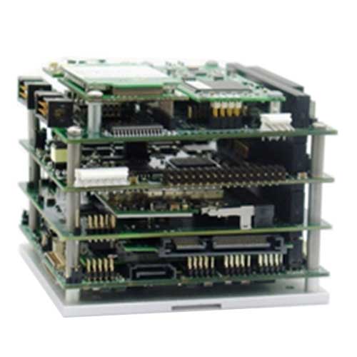
A typical PC/104 system (commonly referred to as a “stack”) will include a CPU board, power supply board, and one or more peripheral boards, such as a data acquisition module, GPS receiver, or Wireless LAN controller. A wide array of peripheral boards is available from various vendors. Users may design a stack that incorporates boards from multiple vendors. The overall height, weight, and power consumption of the stack can vary depending on the number of boards that are used.
PC/104 (or PC104) is a family of embedded computer standards which define both form factors and computer buses. PC/104 is intended for specialized environments where a small, rugged computer system is required. The standard is modular, and allows consumers to stack together boards from a variety of COTS manufacturers to produce a customized embedded system. The original PC/104 form factor is smaller than a desktop PC motherboard at 3.550 × 3.775 inches (90 × 96 mm).
A typical PC/104 system (commonly referred to as a “stack”) will include a CPU board, power supply board, and one or more peripheral boards, such as a data acquisition module, GPS receiver, or Wireless LAN controller. A wide array of peripheral boards is available from various vendors. Users may design a stack that incorporates boards from multiple vendors. The overall height, weight, and power consumption of the stack can vary depending on the number of boards that are used.
The distinguishing features of the PC/104 family that make it more suited to embedded systems than motherboards with expansion cards are:
Compact size (90 x 96 mm)
No backplane – modules stack together like building blocks
Interoperability with boards from numerous manufacturers
Based on familiar PC technology for ease of design and development
Rugged construction: stacking bus connectors and corner mounting holes
The PC/104 bus and form factor was originally devised by Ampro in 1987 and later standardized by the PC/104 Consortium in 1992. An IEEE standard corresponding to PC/104 was drafted as IEEE P996.1, but never ratified. In 1997, the PC/104 Consortium introduced a newer standard based on the PCI bus. A PCI Express-based standard was introduced in 2008. PC/104-related specifications are controlled by the PC/104 Consortium. There are currently 47 members of he Consortium. The specifications released by the PC/104 Consortium define multiple of Bus Structures (ISA, PCI, PCI Express) and Form Factors (104, EBX, EPIC).
| Specification | Initial Release | Bus Communication |
|---|---|---|
| PC/104 | 1992 | ISA (AT and XT) |
| PC/104- Plus | 1997 | ISA and PCI |
| PCI-104 | 2003 | PCI |
| PCI/104-Express and PCIe/104 | 2008 | PCI and PCI Express |


PC/104
The original PC/104 bus derives from the ISA bus. It includes all the signals found on the ISA bus, with additional ground pins added to ensure bus integrity. Signal timing and voltage levels are identical to the ISA bus, with lower current requirements. The PC/104 specification defines two versions of the bus, 8-bit or 16-bit. The 8-bit version corresponds to the IBM XT and consists of 64 pins. The 16-bit version corresponds to the IBM AT and adds 40 additional pins, bringing the total to 104 (hence the name “PC/104”).
PC/104-Plus
The PC/104-Plus standard adds support for the PCI bus, in addition to the ISA bus of the PC/104 standard. The name is derived from its origin: a PC/104-Plus module has a PC/104 connector (ISA) plus a PCI connector. The standard defines a 120-pin connector for the PCI bus, located on the opposite side of the board from the PC/104 connector. PC/104-Plus CPU boards provide active communication on both buses, and are capable of communicating with both ISA and PCI peripheral cards. On PC/104-Plus peripheral modules, the PC/104 connector is simply a passive connector for stackability; the module actively communicates on the PCI bus only. As a corollary, a PC/104-Plus peripheral module may not be used with a PC/104 CPU board. However, a PC/104-Plus CPU board may be used with a PC/104 peripheral module.
PCI-104
The PCI-104 form factor includes the PCI connector, but not the PC/104 connector, in order to increase the available board real estate. Even though the PCI connector has 120 pins instead of 104, the established name was kept. Since the ISA bus is omitted, a PCI-104 board is incompatible with PC/104 peripheral module. However, PCI-104 and PC/104-Plus are compatible, since they both utilize the PCI bus. Most PC/104-Plus boards can be manufactured as PCI-104 by simply not populating the PC/104 connector.
PCI/104-Express
The PCI/104 Express specification incorporates the PCI Express bus (PCIe) in addition to the previous-generation PCI bus. The specification defines a 156-pin surface mount connector for the PCI Express signals. The new connector occupies the same board location as the legacy PC/104 ISA connector. In addition to PCI Express, the specifications also define pins on the connector for additional modern computer buses, such as USB, SATA, and LPC. The PCI/104-Express specification currently defines two possible pinouts for the PCIe connector:
• Type 1 offers four x1 PCI Express links, two USB 2.0 ports, and one x16 PCIe link.
• Type 2 offers four x1 PCI Express links, two USB 2.0 ports, two PCIe x4 links, two USB 3.0 ports, two SATA ports, and LPC.
CPU boards and peripherals may be designed as Type 1, Type 2, or Universal (which only uses the common subset of signals between the two types, PCIe x1 and/or USB 2.0). The Type 2 pinout was not introduced until Version 2.0 of the specification (released in 2011). PCI/104-Express products introduced prior to 2011 will be either Type 1 or Universal, but may not be explicitly labeled as such. A Type 1 bus is incompatible with Type 2 peripherals, or vice versa. The specification requires the system to remain in reset and not boot in the case of a Type mismatch (no physical damage will occur). Universal peripheral boards may be used with either Type 1 or Type 2 pinouts. Because the PCIe bus connector is surface-mount, not through-hole, it is also possible for a board to use different bus pinouts on the top side of the board vs the bottom side. For example, a CPU board may have a Type 1 bottom PCIe connector and a Type 2 top PCIe connector. Such a CPU board would be compatible with Type 1 and/or Universal peripherals on the bottom, and compatible with Type 2 and/or Universal peripherals on the top. Similar to PC/104-Plus, a PCI/104-Express CPU boards will provide active communication on both PCI and PCIe buses. A PC/104-Express CPU board may be used with PCI-104 and PC/104-Plus peripheral modules. However, a PCI/104-Express peripheral module will communicate on the PCIe bus only; the PCI connector is simply a pass-through connector for stackability. A PC/104-Express peripheral module may not be used with a PCI-104 or PC/104-Plus CPU board (unless an ISA bridge device is used).
PCIe/104
PCIe/104 is similar to the PCI/104-Express standard, but omits the legacy PCI bus to increase available space on the board (similar to the relationship between PC/104-Plus and PCI-104). The PCI Express connector location and pinout options the same as PCI/104-Express (both Type 1 and Type 2). Because the PCI bus connector is omitted, a PCIe/104 board is incompatible with PC/104-Plus and PCI-104 systems (unless a PCIe-to-PCI bridge device is used).


