MicroTCA Architecture
![]()
MicroTCA Architecture

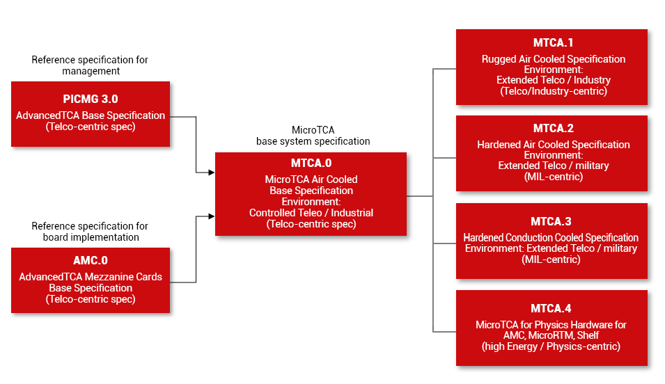
MicroTCA is a modular, open standard for building high performance switched fabric computer systems in a small form factor. At its core are standard Advanced Mezzanine Cards (AMC’s – described here: AdvancedMC) which provide processing and I/O functions. Hundreds of different AMC’s are commercially available. MicroTCA systems are both physically smaller and less expensive than AdvancedTCA systems, although their internal architectures are largely the same. MicroTCA was originally intended for smaller telecom systems at the edge of the network but has moved into many non-telecom applications, with standardized, ruggedized versions becoming popular in mobile, military, telemetry, data acquisition, and avionics applications.
The core specification, MTCA.0, defines the basic system, including backplane, card cage, cooling, power, and management. A variety of different sized AMC modules are supported, allowing the system designer to use as much or as little computing and I/O as necessary. Subsidiary specifications (MTCA.1, MTCA.2, MTCA.3 and MTCA.4) define more ruggedized versions specifically suited for mil/aero and other demanding physical environments. These designs have been verified through thorough rigorous environmental testing and the test reports are available.
![]()
MicroTCA is a modular, open standard for building high performance switched fabric computer systems in a small form factor. At its core are standard Advanced Mezzanine Cards (AMC’s – described here: AdvancedMC) which provide processing and I/O functions. Hundreds of different AMC’s are commercially available. MicroTCA systems are both physically smaller and less expensive than AdvancedTCA systems, although their internal architectures are largely the same. MicroTCA was originally intended for smaller telecom systems at the edge of the network but has moved into many non-telecom applications, with standardized, ruggedized versions becoming popular in mobile, military, telemetry, data acquisition, and avionics applications.
The core specification, MTCA.0, defines the basic system, including backplane, card cage, cooling, power, and management. A variety of different sized AMC modules are supported, allowing the system designer to use as much or as little computing and I/O as necessary. Subsidiary specifications (MTCA.1, MTCA.2, MTCA.3 and MTCA.4) define more ruggedized versions specifically suited for mil/aero and other demanding physical environments. These designs have been verified through thorough rigorous environmental testing and the test reports are available.
MicroTCA system is defined as a collection of interconnected elements consisting of at least one AdvancedMC, at least one MicroTCA Carrier Hub (MCH), and the interconnect, power, cooling, and mechanical resources needed to support them. As an example, a typical MicroTCA system consists of up to twelve AdvancedMCs, one (and optionally two for redundancy) MCHs, Power Modules (PMs) with optional redundancy and load sharing, a cooling subsystem (again, optionally redundant), an interconnect (typically a Backplane), and the mechanical elements comprising a Subrack and Shelf. AdvancedMCs are the primary component of MicroTCA. The ability to use any AdvancedMCs that conform to the AdvancedMC standard without modification in MicroTCA is an overarching goal of this standard. Examples of AdvancedMCs that could be installed into a MicroTCA Shelf include CPUs, Digital Signal Processing devices, packet processors, storage, and various sorts of I/O AdvancedMCs (including metallic and optical line units, RF devices and interfaces to other boxes). MicroTCA offers a significant advantage because the same AdvancedMCs that connect directly to the MicroTCA Backplane can also be equipped on an AdvancedTCA Carrier Board (PICMG 3.0).

 MicroTCA system is defined as a collection of interconnected elements consisting of at least one AdvancedMC, at least one MicroTCA Carrier Hub (MCH), and the interconnect, power, cooling, and mechanical resources needed to support them. As an example, a typical MicroTCA system consists of up to twelve AdvancedMCs, one (and optionally two for redundancy) MCHs, Power Modules (PMs) with optional redundancy and load sharing, a cooling subsystem (again, optionally redundant), an interconnect (typically a Backplane), and the mechanical elements comprising a Subrack and Shelf. AdvancedMCs are the primary component of MicroTCA. The ability to use any AdvancedMCs that conform to the AdvancedMC standard without modification in MicroTCA is an overarching goal of this standard. Examples of AdvancedMCs that could be installed into a MicroTCA Shelf include CPUs, Digital Signal Processing devices, packet processors, storage, and various sorts of I/O AdvancedMCs (including metallic and optical line units, RF devices and interfaces to other boxes). MicroTCA offers a significant advantage because the same AdvancedMCs that connect directly to the MicroTCA Backplane can also be equipped on an AdvancedTCA Carrier Board (PICMG 3.0).
MicroTCA supports six different mechanical sizes of AdvancedMCs. The largest is the Double Full-Size (formerly Full-Height, Double-Width) AdvancedMC, which occupies a mechanical volume of 148.8 x 28.95 x 181.5 mm. This volume can be subdivided into some number of smaller AdvancedMCs, which allows to the functions to be better partitioned onto Modules. MicroTCA requires a Backplane into which the AdvancedMCs and other elements are plugged. High performance connectors of several types are specified by MicroTCA: AdvancedMC Backplane Connectors at each AdvancedMC position bring the signals from the AdvancedMC’s card edge connector into the Backplane. Another connector type, called the MicroTCA Carrier Hub Connector, is used to connect an MCH to the backplane to carry the signals to multiple AdvancedMCs. These connectors are optimized to carry high speed serial signals (supporting bit rates over 10 Gb/s). Power Module Input Connectors are used to bring the input power to the Power Modules. Power Module Output Connectors carry high current power supply connections and various control and management signals from the Power Modules to the Backplane.
| Compact Size 3 HP | Mid-size 4 HP | FUll-size 6 HP | |
|---|---|---|---|
| Single (width) Modules | 73.8 x 13.88 x 181.5 | 73.8 x 18.968 x 181.5 | 73.8 x 28.95 x 181.5 |
| Double (width) Modules | 148.8 x 13.88 x 181.5 | 148.8 x 18.96 x 181.5 | 148.8 x 28.95 x 181.5 |
CHASSIS
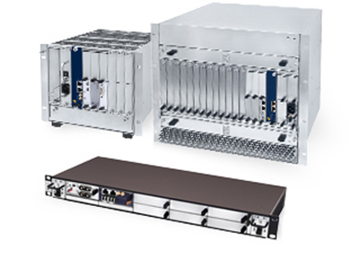
A MicroTCA chassis is more than just an enclosure that provides the physical support to the MicroTCA carrier, management modules, AMCs, Power Modules, Cooling Units and other peripherals. The chassis, sometimes called shelf or crate, provides a managed platform to support a MicroTCA carrier. A MicroTCA shelf along with the Carrier Hub, Backplane, Power Module and Cooling Units provide the necessary framework to build a MicroTCA application. Most MicroTCA chassis are designed for standard 19” racks.
COOLING SYSTEM
MicroTCA Shelves can have high power density. A set of Cooling Units ensures that enough air is forced through the AdvancedMC, PM, and MCH air pathways to keep their temperature within a safe thermal envelope. These Cooling Units typically consist of several individual fans or blowers working in parallel to move an appropriate amount of air at the required pressure. Control systems in the Shelf Manager and Cooling Unit can dynamically adjust the fan speeds in order to provide enough cooling for the given environmental condition, minimizing component wear and acoustic noise. MicroTCA Shelves may use different cooling approaches, such as conductive cooling or natural convection.
ADVANCED MEZZANINE CARDS (AMC)
The AMC standard was originally developed for ATCA systems and is one of the key concept of the MicroTCA architecture. AMCs are implemented as mezzanine in an ATCA system but they are implemented as mini-blades in the MicroTCA system. AMCs allow the MicroTCA functions to be implement in a modular structure and also allow the application to be scalable. AMCs will contain the hardware and software for user functionality (processing and I/O).

MCH
A MicroTCA Carrier Hub or MCH is the main management module that enables and controls different modules of the MicroTCA® system. The MCH is also responsible for data switching between the modules. The MCH can be integrated into the chassis or available as a standalone unit. The standalone MCHs are implemented in AMC form factor and can be easily plugged into a MicroTCA chassis, similar to an AMC. In addition to management of the MicroTCA system, the MCH may provide an IP interface of the System Manager. The MicroTCA specifications allow up to 2 MCH for high availability applications. IPMI is the default management interface used in the MicroTCA systems. The IPMI uses a set of Intelligent Platform Management Bus (IPMB) such IPMB-0 and IPMB-L to provide the required management interfaces.
The system manager is the highest management level of a MicroTCA system. The main function of a System Manager is to provide visual interface to the users of the MicroTCA systems through an IP interface. This IP interface is routed to the Shelf Manager and the Carrier Manager. The interface allows the users to monitor and configure the system level settings and also to get the status of individual modules.
A shelf manager can manage up to 16 carriers and usually is implemented in the MCH. A System Management Software Application can be used to control, manage and monitor platforms. The software application provides an easy-to-use Graphical User Interface with several features for monitoring, trouble shooting and easy integration of these platforms.
A Carrier Manager is the management unit that is responsible for managing a single MicroTCA carrier, which is implemented with the combination of a MCH and a Backplane. The terminology reflects the fact that in ATCA systems the AMCs would be mounted on a carrier so the MCH+Backplane effectively replace that carrier.


A passive interface that provides the required data, management and power connections to the MicroTCA modules. The Backplane along with the MCH provide the virtual carrier interface to the AMCs. The Backplane also store carrier field replaceable unit (FRU) data that is used by the MCH to initialize correct interfaces when a new module is inserted into the chassis. A typical MicroTCA system can support up to seven switched fabrics to provide the required interconnectivity, but each AMC will only use one fabric. The Backplane may use the same ports to support different fabrics but the MCH is responsible for fabric switching.
The Backplane can be designed for a specific application with fewer fabrics or a generic Backplane to support multiple applications. This interconnect consists of a central switch and a number of high speed serial Lanes to each AdvancedMC position. Lanes on MicroTCA are differential high speed Serializer/Deserializer interconnects (SerDes), with bandwidth capability of at least 3.125 Gb/s in each direction. Although some MicroTCA implementations using inexpensive connectors and backplanes will run these Lanes at slower rates such as 1 Gb/s, many MicroTCA Shelves will allow these bit rates to increase to beyond 10 Gb/s per Lane. Fabrics are high speed data connection links in a MicroTCA system. Commonly supported fabrics are GbE, 10 GbE, Infiniband, Serial Rapid I/O and Optic Fiber. The interconnect protocol used in MicroTCA depends upon the specific format expected by the AdvancedMCs and implemented on the MCHs fabric. The fabric component of an MCH is the hub of a star network. Two MCHs are required to implement a dual-star network. In some MicroTCA Shelves, there are supplementary paths directly from each AdvancedMC position to other AdvancedMC positions, permitting the construction of supplemental mesh interconnects and special I/O structures, in addition to the dual star supported by the MCH fabrics.
In addition to the MCH, a power infrastructure is required for a MicroTCA Carrier. Power is delivered to a MicroTCA Shelf through either connections to AC mains voltage or to the +24, -48, or -60 Vdc supplies typical of telecommunication installations. The power control block splits, switches, distributes, and protects this +12 V source for the AdvancedMCs. The Power Module also produces, controls, and monitors multiple branches of +3.3 V Management Power for radial distribution to the AdvancedMCs, MCHs, PMs, and Cooling Units. The Power Subsystem consists of one or more Power Modules. If extra capacity or redundancy is required, up to four Power Modules can be managed in a MicroTCA Shelf. In Redundant Power Module configuration, it will automatically take over the Power Channel responsibilities of a failed Primary Power Module. PMs have circuitry to detect the presence of AdvancedMCs, MCHs, and CUs, and to energize individual power branches. Power Modules also monitor the power quality of each branch and protect against overload.

The PICMG MicroTCA.2 specification addresses the needs of severe shock, vibration, and thermal environments typical of many military air, land and sea as well as rugged industrial applications. The specification defines a modular open systems approach for hardened hybrid air/conduction cooled computer systems. It was developed based on key input from military vendors such as BAE Systems, and includes well-defined test procedures for a consistent reading of vendor compliance. MicroTCA.2 modules of all power levels benefit from the hybrid air/conduction cooling (hybrid cooling) approach, in which conduction allows thermal sharing among modules and with the chassis. This thermal sharing effect allows additional surface area to be exposed to the airflow through the chassis to more effectively dissipate the system’s total thermal load. Forced-air convection yields the dominant cooling effect in MicroTCA.2 systems, yet there is a significant secondary conduction cooling benefit associated with the module clamshell and innovative wedge lock designs. By taking advantage of complementary conductive heat transfer through finned clam-shelled module surfaces and aluminum chassis sidewalls, as well as heat sharing between adjacent chassis slots, the MicroTCA.2 hybrid cooling solution effectively provides increased thermal margin over other MicroTCA modes in environments with higher air temperature or decreased airflow.
Scientific high-performance computers used in fields of study including particle and photon physics, astronomy, nuclear fusion, high-energy technology, medical science etc. must capture and process huge quantities of measuring values. At the same time, the trend in particle accelerators will likely move towards focusing more on using distributed computers. The modern keyword describing such a computer network is ‘cloud computing’. MicroTCA is very well suited for utilization at any point in the system process. MicroTCA for Physics combines the advantages of MicroTCA with Rear I/O. MicroTCA controls remote data capture via a remote management function. The data is delivered by the relevant detectors and sensors both in standardized format – for instance in the 4 to 20 mA range – or in any other format and then needs to be passed on to the computer for further processing. Modern telco system architectures (AdvancedTCA, MicroTCA) feature serial, switched point-to-point connections and thus offer extremely high data transfer rates in the GB/s range. This high bandwidth is complemented with optimal cooling up to 80 watts dissipation loss for each AMC and includes integrated hardware management functions plus the previously mentioned modular design. The use of standard AMCs also meets the requirement of employing the same hardware and software in high-performance systems. The AMCs can be integrated into AdvancedTCA as well as into MicroTCA systems, thus making it possible to achieve the power density offered by AdvancedTCA in MicroTCA. While modules are directly pluggable, the electronic keying principle prevents accidental connection of an incompatible AMC module. This provides a high level of process reliability and contributes to keeping the system maintenance friendly. For these reasons, the physics community decided on this technology as a forward-looking platform for high-performance basic research applications.


