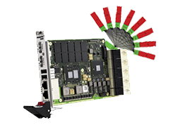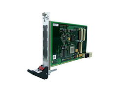
It is based on the established PICMG 2.0 CompactPCI standard which uses the parallel PCI bus for communication among a system’s card components.
In contrast to this, CompactPCI Serial uses only serial point-to-point connections.
CompactPCI Serial was officially adopted by the PCI Industrial Computer Manufacturers Group PICMG as PICMG CPCI-S.0 CompactPCI Serial in March 2011.
With CompactPCI Serial, the CompactPCI architecture moves to serial high-speed interconnects, and more data can be transferred at higher speeds using PCI Express. Additional high speed interfaces, including Ethernet, SATA, and USB are supported.
A typical configuration of one system slot and up to eight peripheral slots does not need switches and bridges.
Using the proven 19” mechanics of the IEC 1101 family, proven with CompactPCI and VME, the standard introduces a new rugged additional connector with a signal density of up to 184 pin pairs (on 3U) and transmission frequencies of 12 Gb/s.
Hot Swap of boards during operation is supported, as it was with original CompactPCI.
Each system is organized as follows: a System Slot, usually the CPU and often a complete single board computer, provides 8 PCI Express links, 8 SATA/SAS, 8 USB 2.0/3.0 and 8 Ethernet interfaces plus signals for general system management and up to eight peripheral slots.
The pin assignment of the system and the peripheral slot is congruent. In this way it is possible to plug a system slot board into each peripheral slot to support symmetrical multiprocessing. This is a significant advance over other 3U/6U standards.
Star topologies are supported and each slot is given equal priority: PCI Express, SATA/SAS and USB. All peripheral slots are identical except two that are connected via PCI Express links by 8 lanes.
Ethernet is normally configured as a full mesh. Although alternate topologies are supported.
Transmission is based on the proven standards for copper connections up to 10GbaseT to allow configuration of redundant, safety-critical systems.
This is important for demanding mil/aero, transportation, security, and many medical applications.
| Interface Type | System Slot | Peripheral Slot |
|---|---|---|
| PCI Express | 6 x4 links 2 x8 links (fat pipes) |
1 link, maximum x8 |
| SATA/SAS | 8 channels | 1 channel |
| USB 2.0 | 8 channels | 1 channel |
| USB 3.0 | 8 channels | 1 channel |
| Ethernet 10GBASE-T | 8 channels | Up to 8 channels |
The architecture of CompactPCI Serial is a simple star of one system slot and up to eight peripheral slots, combined with a full mesh for Ethernet. The pin assignment for Ethernet is the same for the system slot and peripheral slots. One pin signals to the plugged-in board whether it is located in a system slot or peripheral slot. This allows to plug a system-slot board (normally a CPU card) also into any peripheral slot. In this case some interfaces are not supported, of course – usually SATA. The Ethernet interfaces are always supported, however. Despite its star topology CompactPCI Serial supports symmetrical multiprocessing with up to nine CPUs in one system – without bridges and without a special backplane. With bridges even more are supported. The usage of a new connector type allows for the necessary high signal density and high transmission frequencies of 12 Gbit/s and more. The AirMax connector (FCI, Amphenol TCS) offers space for up to 184 pin pairs on a 3U board. The high pin number is especially important for the system slot because of the above-mentioned star architecture of modern computers. It also allows using a multitude of free pins for customized rear I/O on peripheral assemblies. The mechanics of the connector meet the requirements of the IEEE 1101 and the look-and-feel is very much like that of the proven 2-mm-connector of the CompactPCI standard. Compared to CompactPCI, the placement of the plug and receptacle connectors is swapped. The plug connector is placed on the plug-in card, while the receptacle connector is located on the backplane – just as in VMEbus systems. This makes twisted pins on the backplane a thing of the past.
The AirMax connector was specially developed for use in harsh environments. For the plug connector, i.e. the connector on the plug-in card, there are versions that can be mounted side by side. They only have two walls. In other varieties the pins are enclosed by three or four walls.
On a 3U board, there is always one connector with four walls and six pin rows. It is supplemented by several types mounted side by side and having two walls and eight rows. The final connector has three walls and eight rows.
On the whole this makes a plug connector that is protected on all sides and has a crossing wall at the center. This crossing wall supports the stability of the plug-in board, while preventing a CompactPCI Serial board from being plugged into a conventional CompactPCI slot and from twisting the pins there.
CompactPCI Serial: Compared to CompactPCI the plug and receptacle are swapped


